
Small Contraflow Heater Workshop
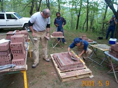
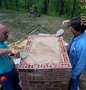
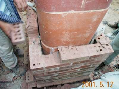
Heater base. Outside finished dimensions are 36" x 24"
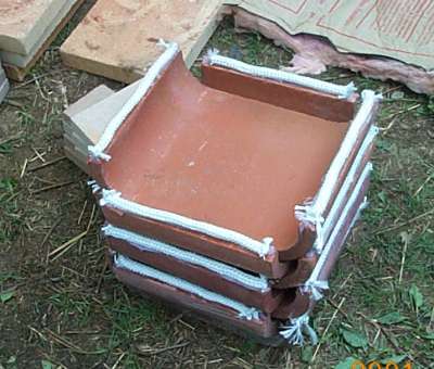
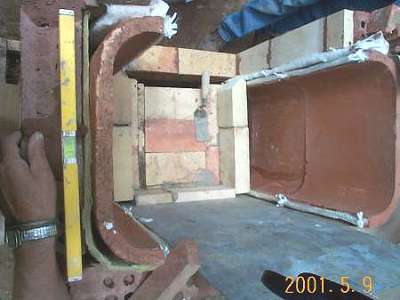
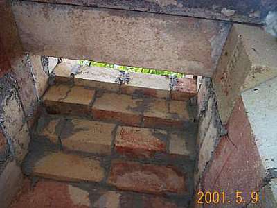
The downdraft channels are lined with clay flue liners. Cross section of downdraft heat exchange channels is 4" x 13.5". Liners were cut from standard 12" x 16" flue liners. Fiberglass rope is siliconed to the liners as to provide the primary expansion joints for the heater.
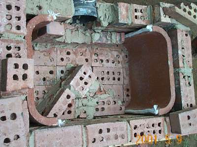
Heater base run. Downdraft channels exit to rear into an 8" round stove pipe. Triangular piece in front is to support firebox floor. Clay bricks are laid up in clay/sand (adobe) mortar.
Firebox floor in place. Note rear expansion joint created by 1/4" mineral wool blanket.

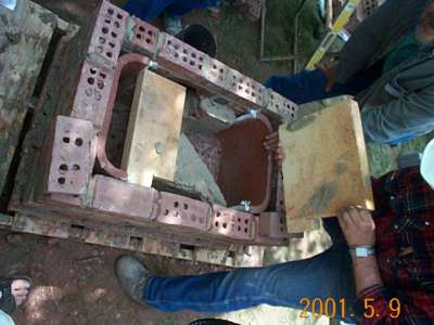
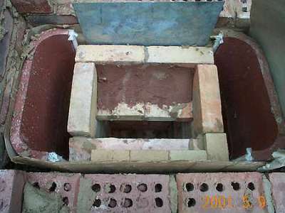
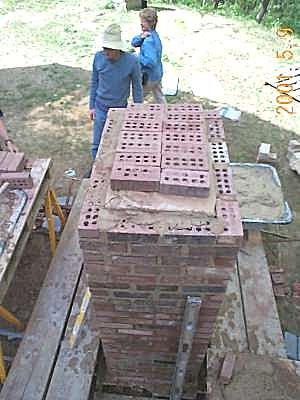
Second set of heat exchange channels in place. Temporary sheet metal in rear keeps expansion joint material in place. Right side and right rear side were done in mineral wool, and left side and left rear side were done in cardboard for heat transfer comparison purposes. Note cardboard being adjusted on left side.
View from above. Note void at corners between mineral wool and brick facing. Some masons slush this solid with mortar to improve heat transfer and gas tightness.
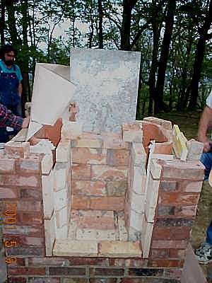
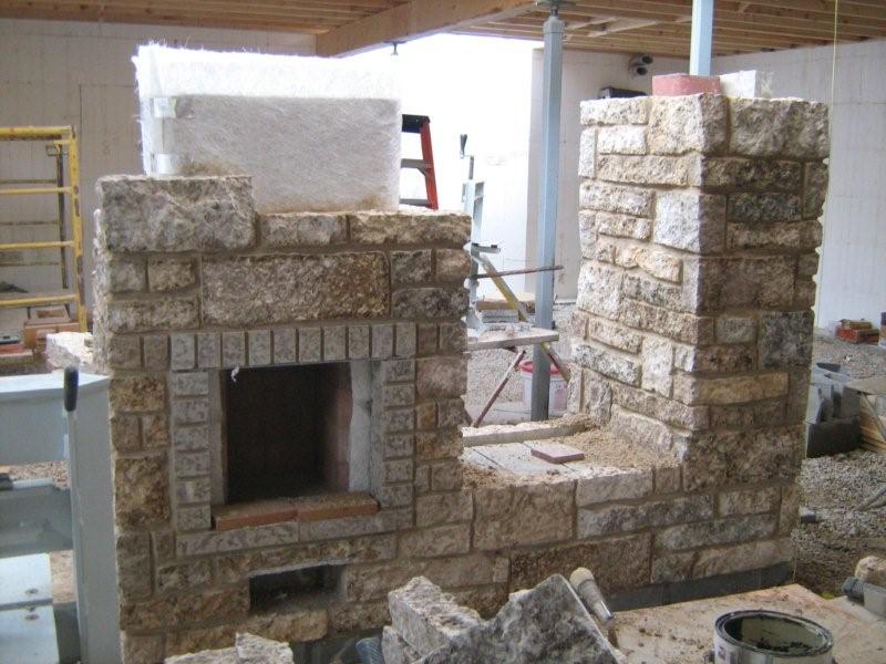
Firebox is built. Rear firebox section consists of a 2.25" firbrick on edge plus a 1.25" firebrick on edge to meet building code requirement for 8" overall wall thickness. Different expansion joint materials visible left and right.
Firebox at throat level.
Firebox throat detail.
Throat viewed from inside.
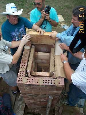
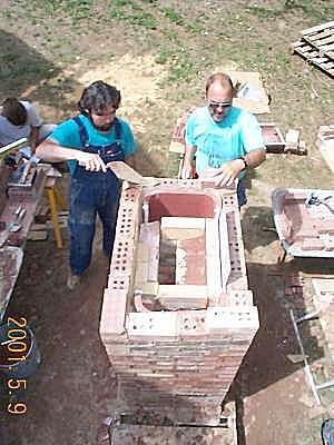
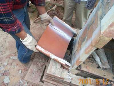
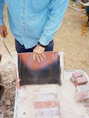
Firebox ceiling slabs being installed.
Ceiling slabs are capped with mineral wool and bricks.
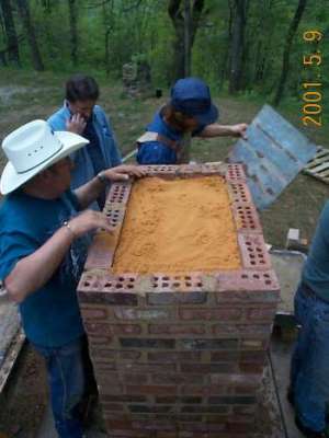
A layer of sand is added.
And a final mortar cap. Often, cement mortar is used for this final cap and a piece of mesh is embedded in it.
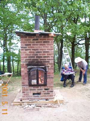
A curing fire was lit in the heater. Once the heater was completely dry, safety testing commenced. Five full loads of oak with 13% moisture content were fired back to back. Surface temperatures on the heater exceeded 300 deg. F.

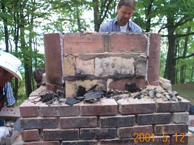
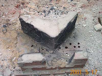
The next day, the heater was dismantled. To most people's surprise, only the top clay flue liners had minor cracking at one top corner.
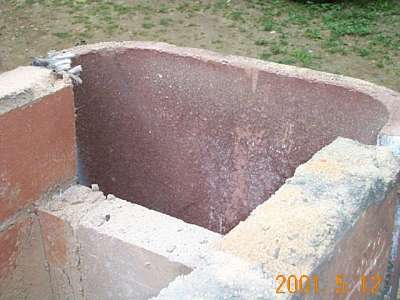
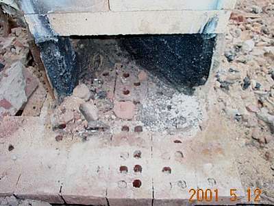
View from inside. The flue liners are burned completely clean at the top of the heater.
The mineral wool insulation is intact.
Rear of heater. Cardboard char on the left side, intact mineral wool on the right. Testing indicated that the mineral wool side ran cooler than the cardboard side.
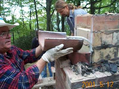
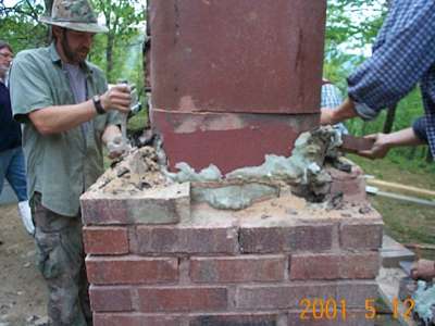
Dismantling the channels. The silicone had vaporized, indicating that temperatures throughout the flue liner exceeded 700 deg F.
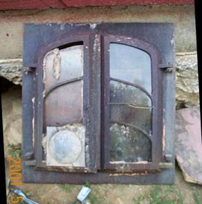
Jerry brought along an old door that was used at Lopez Labs for most of the original heater testing 8 years ago. It was an early prototype casting for the Heat-Kit door. We called it the "Urban Decay" model.
Lower heat exchangers are completely intact with no indications of stress.
Air void visible at corners. With mortar slushing, surface temperatures would have been even higher.
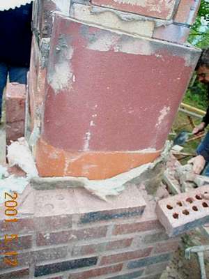
Middle channel. Original liner was cracked and siliconed back together prior to installation. White streaks are residue from vaporized silicone.
Lower liner. Silicone is intact. Note slight soot deposit that would have been present in all liners but burned off. Edge of soot trace shows temperature distribution along liner, i.e., slightly hotter at the center.
Base run. Slight blackening, but no deposits. Small amount of fly ash at right.
Dismantling the firebox. Two types of clay mortar were used for the firebox construction: Redart and Superior Clay fireclay. The Superior Clay fireclay had a better bond.
View of base run from rear.
No Comments